Thursday, March 31, 2011

NETWORK TRANSMISSION MEDIA: Part2

Coaxial Cables


Coaxial cables commonly referred to as coax cables, derive their name from their structure. The structure is designed in a way that the two conductors share a common axis.
The following figure shows the structure of a coaxial cable.


In the preceding figure, the structure of the coaxial cable consists of a center conductor responsible for transmitting data. The outer conductor or shield protects this center conductor from EMI, ensuring that data transmission is not disrupted. The insulator provides a uniform space between the two conductors. A plastic jacket covers the cable and protects it from damage.

Coaxial cables provide effective protection against EMI during data transmission. This high level of resistance to EMI is attributed to the structure of the coaxial cable, which consists of a conductor made up of thick copper or stranded wire, which is covered with an insulator coating. An outer conductor made up of a braided metal shield covers this insulator coating.
The following are the most commonly used categories of coaxial cable:
RG-6
RG-8
RG-11
RG-58
RG-59


Coaxial cables are easy to install as compared to twisted pair cables, support higher transmission rates (10 Mbps and above). In addition, because coaxial cables suffer from lower attenuation rates than TP-based cables, coaxial cables effectively ranges up to 1 Km, which is a much higher range than either of the TP cables. Another advantage of coaxial cables is that although they use copper-based wire, they are less sensitive to EMI and other electrical interferences.

The main limitation of coaxial cables is that they are more expensive than TP cables. In addition, because of the hard covering of coaxial cables, the reconfiguration and reinstallation of the current network setup becomes difficult.

Fiber Optic Cables

Fiber optic cables are based on the fiber optic technology, which uses light rays or laser rays instead of electricity to transmit data. This makes fiber optic a suitable carrier of data in areas that are prone to high levels of EMI or for long-distance data transmissions, where electrical signals may be significantly distorted and degraded.

The components of a fiber optic cable include the light-conducting fiber, cladding, and insulator jacket. The cladding covers the core fiber and prevents the light from being reflected through the fiber and the insulating jacket. The outer covering (or the insulator jacket) is responsible for providing the required strength and support to the core fiber as well as for protecting the core fiber from breakage or high temperatures.
The following figure shows a cross-section of a fiber optic cable.

Fiber Optic Cable


Fiber optic cables can be differentiated into the following two categories:


Single mode cables: These cables use single mode fiber, which provides a single path for the light rays to pass through the cable, as shown in the following figure. A single mode fiber is suitable for carrying data over long distances.

Single Mode Cables

Multimode cables: These cables use multimode fiber, which provides multiple paths for light rays to pass through the cable. The following figure shows a multimode fiber:

Multimode Cable

Because light rays are unaffected by large distances or environment, the signals do not attenuate or suffer from EMI or other interferences. This makes multimode cables extremely safe and prevents outsiders from eavesdropping on an ongoing transmission. In addition, optical cables can support high bandwidths, from 100 Mbps to 2 Gbps. As a result, a network setup using fiber optic cabling can expand up to 10 Kms, without any problems. These facts have made fiber optic cabling popular on the networking market today.
Fiber optic cabling also has a few limitations. It is the most expensive cabling type. It is also cumbersome to install fiber optic networks because fibers are damaged if they are bent sharply.


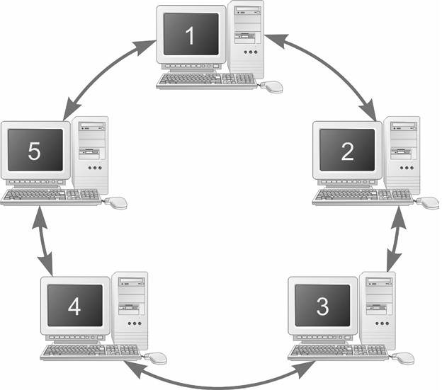
Working of the Token Ring Network
Token Ring is a network architecture developed by International Business Machines (IBM). It is also a protocol, IEEE 802.5, developed by Institute of Electrical and Electronics Engineers (IEEE), which serves as a standard for IBM Token Ring.

When a token ring network is initiated, all the nodes on the network negotiate and decide upon the node that will monitor the network to ensure that the network traffic passes smoothly.

Data on the token ring network is transmitted in the form of tokens. The tokens are passed in a unidirectional way. When the destination node receives the message, it marks the message as “Read”. The message is passed in the ring and it comes back to the sender. The sender checks the message read mark to identify that the message was read by the destination node.

On the token ring network, only the node that possesses a token can transmit data. Each node on the network is allowed to hold the token for a specified time period. If the node holding the token does not have any data to transmit, it passes the token to the next node on the ring.


Click Here To See Part1
Keep it up!
    

NETWORK TRANSMISSION MEDIA: Part1

NETWORK TRANSMISSION MEDIA


The physical channel that connects network components, such as nodes and printers, is known as the transmission medium. The transmission medium determines the speed and connectivity and; as a result, the overall performance of the network and the investments required to set up the network.
The types of transmission media include:


  • Cables: Cables connect networks over relatively short distances. The different types of cables that can be used to set up networks include twisted pair cables, coaxial cables, and fiber optic cables.

  • Wireless: Wireless transmission carriers connect mobile computers, such as laptops and personal digital assistants (PDAs), over a network. Various types of wireless transmission media include infrared, radio wave, and microwave transmissions.


Cables


Cables are the conventional media that are used to set up networks. When deciding on the type of cable to be used, you need to consider factors, such as the environment in which the cabling is to be implemented and the overall speed requirement of the network. After determining the requirements, you can choose the cabling that suits your requirements.

One of the major concerns in cabling is the environment in which the cables are set up. Some areas, such as factories and power plants, might generate electro-magnetic radiations, which may corrupt the data transmission. The disturbances are referred to as electro-magnetic interference (EMI). In electro-magnetic sensitive areas, the type of cable used should be such that transmissions are protected against EMI or are at a distance from radiations. In addition, other factors, such as the characteristics of the cable and network requirements, determine the type of cable that should be selected to install the network.


Twisted-Pair Cables


Twisted-pair (TP) cables are the most widely used cables for setting up networks. A twisted-pair cable uses copper wires, which are good conductors of electricity. However, when two copper wires are placed in close proximity, they interfere with each other's transmission, resulting in EMI (electro-magnetic interferences), known as crosstalk. In a twisted-pair network cable, multiple pairs of wires are twisted around each other at regular intervals. The twists negate the electro-magnetic field and reduce network crosstalk.

Twisted-pair cables are easy to set up, economical, and widely available media for network transmission. However, this media cannot be used in areas where network security is crucial or the network setup is close to electronically-sensitive equipments that may prove to be potential sources of EMI.
Twisted-pair cables are of two types:

  • Unshielded Twisted Pair Cables (UTPs)
  • Shielded Twisted Pair Cables (STPs)

Unshielded Twisted Pair Cables

Unshielded Twisted Pair cables are the most commonly used cabling media. This type of cabling is generally used in telephone systems.
UTP cables consist of a set of twisted pairs that are covered with a plastic jacket, as shown in the following figure:

Unshielded Twisted Pair Cable


However, this plastic jacket does not provide any protection against EMI. To ensure that data transmission is not disrupted due to EMI, UTPs are not installed in close proximity to electro-magnetic devices.
Another problem related to these cables is that the signals the UTPs carry undergo rapid attenuation. As a result, the recommended length of these cables is not more than 100 meters.


Although UTP cables are sensitive to interference, they are highly economical and widely available as compared to other cables and transmission media. In addition, UTP cables are easy to install. All these factors have contributed to the popularity of UTPs in the field of networking.
Due to their wide availability, UTP cables have been standardized by Electrical Industries Association (EIA) and are available in various categories called CAT ratings.


Shielded Twisted Pair Cables
Shielded Twisted Pair cables consist of multiple twisted pairs (TPs) surrounded by an insulator shield. This shield serves to protect the copper-based core from EMI. This insulator shield, in turn, is covered with a plastic encasement, as shown in the following figure:

Shielded Twisted Pair Cable


STP cables are protected against EMI by two layers. As a result,they are less sensitive to EMI and interference. However, STP-cable shielding should be grounded to prevent interference in the cable. In addition, compared to UTP, STP cables offer higher transmission rates – from 16 Mbps to 155 Mbps.
Despite high transmission rates, STP cables have a number of limitations. They are expensive and not as widely available as UTP and coaxial cables. STP cables are not implemented commonly on large networks because of its incompatibility with the normal telephone cabling. They are mainly restricted to the Token Ring LAN setup.


Part2 will deal with Token Ring and, and other types of cables existing on the networking industry.
Keep it up!
   

Wednesday, March 30, 2011

Logical Network Topologies& Network Control Strategies

Logical Topologies& Network Control Strategies

Logical Topology

Logical topologies describe how network messages travel and get delivered across a network. It would be easy to visualize the connections of physical topologies if the nodes simply connected to each other. However, this is not the case in newer LAN arrangements. This is due to the fact that most LAN installations employ connection devices, such as hubs and routers, which alter the appearance of the actual connection scheme.

Therefore, the logical topology will not match the appearance of the physical topology. The particulars of the connection scheme are hidden inside the connecting device. As an illustration, the following figure shows a typical network connection scheme using a router. The physical topology appears as a star. However, the internal wiring of the connecting router provides a logical bus topology.
It is not uncommon for a logical ring or mesh topology to be implemented in a physical star topology.

Logical Network Topology


Network Control Strategies

When you begin to connect computers to other computers and devices over a LAN so that they can share resources and data, the issue of how and who will control the network comes up. In some applications, such as developing a book like this one, it is good for the author, artists, and pagination people to be able to share access to text and graphics files, as well as access to devices such as printers. However, in a business network, companies must have control to provide access to sensitive information and company resources.


Control of a network can be implemented in two ways:

  • As a peer-to-peer network where each computer is attached to the network in a ring or bus fashion and is equal to the other units on the network.
  • As a client/server network where dependent workstations, referred to as clients, operate in conjunction with a dedicated master computer.

The following figure shows a typical peer-to-peer network arrangement. In this arrangement, the users connected to the network can share access to different network resources, such as hard drives and printers. However, the control of the local unit is fairly independent. The nodes in this type of network configuration usually contain local hard drives and printers that the local computer has control of. These resources can be shared at the discretion of the individual user. A common definition of a peer-to-peer network is one in which all nodes can act as both clients and servers of the other nodes under different conditions.

Peer-To-Peer Network
The following figure shows a typical client/server LAN configuration. In this type of LAN, control tends to be very centralized. The server typically holds the programs and data for its client computers. It also provides security and network policy enforcement.

Client-Server Network
In some cases, the client units do not even include a local hard drive or floppy drive unit. The bootup process is performed through onboard BIOS, and no data is stored at the client machine. This type of client is referred to as a diskless workstation.
The major advantages of the client/server networking arrangement include:
  • Centralized administration
  • Data and resource security
Keep it up!
        

Network Topologies Overview

Network Topologies

Network topology is a schematic layout or map of the arrangement of nodes over a network. This layout also determines the manner in which information is exchanged within the network.
However, topologies can be implemented physically or logically.


Bus Topology
In the bus topology, nodes or stations of the network connect to a central communication link. Each node has a unique address along the bus that differentiates it from other users on the network. Information can be placed on the bus by any node. The information must contain network address information about the node or
nodes. Other nodes along the bus ignore the information.

Bus Topology


Ring Topology
In a ring network configuration, the communication bus is formed into a closed loop. Each node inspects the information on the LAN as it passes by. A repeater, built into each ring LAN card, regenerates every message not directed to it and sends the message to the next appointed node. The originating node eventually receives the message back and removes it from the ring.

Ring topologies tend to offer very high data transfer rates but require additional management overhead. The additional management is required for dependability. If a node in a ring network fails, the entire network fails.

Primary Ring Topology

 To overcome this, ring designers have developed rings with primary and secondary data paths as shown in the following figure. If a break occurs in a primary link, the network controller can reroute the data onto the secondary link to avoid the break.

Primary&Secondary Ring Topology

Star Topology
In a star topology, the logical layout of the network resembles the branches of a tree. All nodes are connected in branches that eventually lead back to a central unit. Nodes communicate with each other through the central unit. The central station coordinates the network’s activity by polling nodes, one by one, to determine whether they have any information to transfer. If so, the central station gives that node a predetermined slice of time to transmit. If the message is longer than the time allotted, transmissions are divided into small packets of information that are transmitted over several polling cycles.

Star Topology


Mesh Design
The mesh design offers the most basic network connection scheme. In this design, each node has a direct physical connection to all other nodes in the network. While the overhead for connecting a mesh network topology together in a LAN environment is very high, this topology is employed in two very large network environments, the public telephone system and the Internet.

Mesh Topology
Keep it up!
        

Local Area Network (LAN)

"THIS SITE IS UNDER CONSTRUCTION"

LOCAL AREA NETWORKS

When more than two computers are linked together so that they can share information, a network is formed. Networks in a relatively confined geographical area are called local area networks (LANs), while networks distributed over wider geographical areas are referred to as wide area networks (WANs).


Local area networks (LANs) are systems designed to connect computers in relatively close proximity. These connections enable users attached to the network to share resources such as printers, modems, and other hardware devices on the network.
LAN connections also enable users to communicate with each other to share data among their computers.
When discussing LANs, there are two basic topics to consider, the LAN’s topology (hardware connection method) and its protocol (communication control method).

In concept, a minimum of three stations must be connected to have a true LAN. If only two units are connected, point-to-point communications software and a simple null modem could be employed.

Network topologies are physical connection/configuration strategies. LAN topologies
fall into four types of configurations:

  1. Bus
  2. Ring
  3. Star
  4. Mesh


The following figure shows all four topologies.

Star, Bus, Ring, and Mesh Configurations

Well, the next publication will give more about about network topologies.
Keep it up!